
By:
Paul Francoletti
Director of Product Sales – Mechanical
Published on:
March 13th, 2024
Subscribe now and get the latest blog posts delivered straight to your inbox.
Selecting the Right Manifold Valves for Your Pressure Gauge

By:
Paul Francoletti
Director of Product Sales – Mechanical
Published on:
March 13th, 2024

This article was originally published on January 10, 2022, and was updated on March 13, 2024.
If you work in the oil and gas or chemical industry, or even in a power plant, you know that a manifold valve blocks the flow of fluid in your system so the process media will be isolated from pressure instrumentation. You also know that a block-and-bleed manifold blocks the upstream process media from the instrumentation while allowing the bleeding off (venting) of the remaining fluid from the system on the downstream side of the manifold. But when you need to know which manifold valve is the right one for your specific process, that's where we can help.
Ashcroft is a leading authority in pressure instruments and the accessories that help them operate at peak performance. As the senior product manager for this segment of our line, I have had the opportunity to train many customers and distributors on this very subject.
Read this article to learn the various manifold valves, how they are different and the mounting options you can choose from. When you are done, you will also find additional resources that may be of interest to you.
What are the common configurations of a manifold valve?
Manifold valves are available in 1-, 2-, 3- and 5-valve configurations. All these manifolds are shut-off devices designed for the removal of the attached instrument. This allows the pressure instrument to be replaced or recalibrated without experiencing a loss in process media.
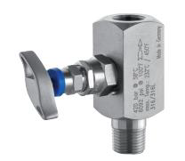
1-Valve manifolds: block or isolate pressure instrumentation.
A 1-valve manifold is designed in a single block with male or female screwed inlet and outlet ports to isolate pressure instrumentation from the process media. The single block valve is designated with a blue handle.
They are available in 316 stainless steel with valve packing in PTFE as a standard. Materials such as Hastelloy® C and Monel® are available upon request, as is graphoil valve packing for higher temperature applications.
Figure 1: 1-Valve manifold.
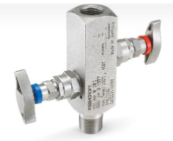
2-Valve manifolds: block and bleed with pressure instrumentation.
A 2-valve manifold is designed in a single block with male or female screwed inlet and outlet ports, combining an isolation valve and calibration/vent (bleed) valve. The block valve is designated with a blue handle, and the bleed valve is designated with a red handle.
They are available in 316 stainless steel with valve packing in PTFE as a standard. Materials such as Hastelloy® C and Monel® are available upon request, as is graphoil valve packing for higher temperature applications.
Valves are available in the most common in-line type or L-shaped or Y-shaped configurations.
Figure 2: 2-Valve manifold.
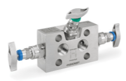
3-Valve manifolds: block and equalize pressure with differential pressure instrumentation.
A 3-valve manifold consists of 1 equalizing valve and 2 blocking valves. One blocking valve at the high-pressure side and the other at the low-pressure side are designated with blue handles. The two block valves are open while the equalizing valve is closed during normal operation.
The block valves provide instrument isolation, and the one equalizing valve is designated in green and positioned between the high and low process connections of the pressure instrument to provide equal pressures on both sides.
Figure 3: 3-Valve manifold.
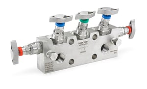
5-Valve manifolds: block, bleed and equalize pressure with differential pressure instrumentation.
A 5-valve manifold consists of 1 equalizing valve, 2 block valves and 2 bleeding valves. One blocking valve at the high-pressure side and the other at the low-pressure side are designated with blue handles.
The bleed valves are designated in red and allow for the venting of trapped pressure through a tube to some remote location.
The one equalizing valve is designated in green and positioned between the high and low process connections of the pressure instrument to provide equal pressures on both sides. The two block valves are open while the equalizing valve and bleed valves are closed during normal operation.
Figure 4: 5-Valve manifold.
Which manifold valve is right for your differential pressure instrument?
Ashcroft offers 3- and 5-valve manifolds in different styles based on how they are attached to differential pressure gauges. The most important factors in this mounting are the design of the manifold and the port distance on the manifolds.
Not every manifold is configured to be directly connected to a differential pressure gauge, regardless of the port distance. See Figure 5 below.
- V01 type in a 3- and 5-valve are for remote mounting only.
- V02 type in a 3- and 5-valve are available for both direct and remote mounting.
- V03 type in a 3- and 5-valve are available for direct mounting of differential gauge models 1132 and 1133 only.
Figure 5: Valve manifold attachments.

For direct mounting to the manifold, the instrument port distance on the manifold and the differential pressure gauge must line up. Additionally, the shape or style of the manifold is critical for direct mounting.
Ashcroft provides the V01, V02 and V03 series manifolds in configurations designed for either direct mounting or remote mounting.
Direct Mounting
Refer to Figure 5, which lists each Ashcroft differential pressure gauge and the mounting options for manifolds that are available. All coding lists the standard ½ NPT female process connection. ¼ NPT female process connections are also available for all manifolds.
Attachment options for direct mounting are as follows:
-
The 1132, 1133 F5504 and 5503 are presently the only differential pressure gauges manufactured by Ashcroft that can be directly mounted to either a 3- or 5-valve manifold. In each case, the gauge must have the proper connection size and location as designated in Figure 6.
-
The F5504 must use the ‘DM’ connection code when directly mounting to a 3 or 5-valve V02 type manifold. The 5503 must use a ‘51L’ connection code. The 1132 and 1133 must use a ‘25L’ connection code when directly mounting to the 1132 or 1133 differential pressure gauges. Only lower connection locations for the 1132, 1133, F5504 and the 5503 are available for direct mounting.
-
The 50V023VASS60 and 50V025VASS60 types are specifically designed to mount to the 54 mm port distance on the F5504 and the 5503 gauge. Each of the 3- and 5-valve manifolds is provided with 4 bolts to attach to the F5504 and 5503, as well as 2 Teflon O-rings for each connection port.
-
The F5504 must be coded with the ‘DM’ connection code, and the 5503 must be coded with a ‘51L’ connection code to properly connect directly to the manifold valve.
The 50V033VBSS86 and 50V035VBSS86 type manifold valves have port holes that have a 62.1 mm distance. This allows the ports to match up with the 1132 and 1133 differential pressure gauges.
The ‘86’ instrument connection code is provided on the manifold, which is a ¼ male NPT swivel adapter. This allows for proper connection to the ¼ female NPT (25L) on the differential gauge.
Indirect Mounting
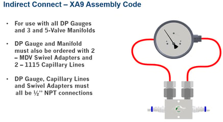
Indirect mounting requires either flexible or rigid piping to be used to connect a pressure instrument to the manifold. To accomplish this connection, Ashcroft utilizes flexible capillary lines used with swivel adapters.
Attachment options for indirect mounting are as follows:
- Ashcroft V01 series manifolds are designed for remote mounting only.
- V02 and V03 series may be either direct or indirect mounted.
- When indirect mounting is required, two 1115 capillary lines and two MDV swivel adapters are required to complete the assembly as illustrated by Figure 2.
The ‘XA9’ connection code is used to allow Ashcroft to properly complete the assembly. Figure 2 shows an 1132 with side connections (not available for direct mounting) attached to the capillaries, attached to the MDV swivel adapters, which are then attached to the manifold. The ‘XA9’ code must also be used when indirect mounting is required for any differential pressure gauge or differential pressure switch.
Liquid filling of the assembly is not required. Please consult an Ashcroft expert for proper coding and pricing on all parts of the assembly required.
Figure 6: Indirect mounting connection.
Connect with us to learn more.
Now that you understand what manifold valves go with what pressure instrumentation, you can research the solution that’s right for your application. If you want to learn about measurement instrument accessories and designing assemblies, view our assembly guide. Or, check out some of these articles for more information about application accessories:
- Do Measurement Instrument Accessories Affect Accuracy?
- What’s the Right Pressure Instrument Mounting Assembly for Me?
- Isolation Ring Assemblies for the Water/Wastewater Industry
You can also contact us directly to talk to one of our industry experts and get all your measuring instrumentation questions answered. In the meantime, download our guide to pressure instrument assemblies:
Paul Francoletti, Director of Product Sales – Mechanical
Paul Francoletti is the Product Sales Leader for process and industrial pressure gauges at Ashcroft. He has spent the past 15 years in numerous roles at Ashcroft ranging from Technical Support, EPC Support Manager and now, Product Leader.


