
Subscribe now and get the latest blog posts delivered straight to your inbox.

This article was originally published on January 24, 2022, and updated on March 3, 2025.
If you work in oil and gas pipelines, chemical plants, refineries or anywhere that will require a thermowell to protect your temperature sensor from the process media, it is important to ensure that the device will work in the application. For instance, wake turbulence caused by your process has the potential to break the thermowell and damage your equipment.
Calculating thermowell wake frequency can help. As a product leader at Ashcroft, with more than 40 years of industry experience, this is a topic that I talk to customers about often. In this article, you will learn what thermowell wake frequency is and how to calculate it. When you are done reading, you will understand the need to have a wake frequency calculation done and be more confident in your thermowell's ability to protect your temperature sensor. Plus, we will share additional resources that will deepen your knowledge of thermowells even further.
What is thermowell wake frequency?
A wake is the region of recirculating flow immediately behind a moving or stationary solid body, caused by the flow of the surrounding fluid. The alternating vortices that occur as the media flows across the shank can create turbulence causing the thermowell to resonate or oscillate. This is referred to as vortex shedding or Von Kármán trail.
The shedding rate is calculated and compared to the natural frequency of the thermowell. If the frequency of the wake is too close to the natural frequency of the thermowell then the vortex shedding can destroy the thermowell, resulting in possible damage to the temperature instrument and your process as the broken shank flows through your system.
How can I calculate the wake frequency of my thermowell?
Ashcroft has developed a Wake Frequency Calculator tool to assist you with the proper thermowell selection. This tool was designed following the ASME PTC 19.3 TW.
Figure 1. Ashcroft® Wake Frequency Calculator screenshot.

What data will I need to input into the thermowell wake frequency calculator?
There are five pieces of your process media data and thermowell dimensions required to run a calculation. Without all the details you cannot run a calculation:
- Velocity: This is the speed of your media, typically measured in feet per second or meters per second. This condition is critical to the calculation as the velocity affects both the lift and drag forces and other stresses applied to the thermowell.
- Density: Mass per volume or specific gravity. The density combined with the velocity comes into play in all calculations.
- Viscosity: The thickness of your media, or a measure of your media’s resistance to shear stress.
- Maximum Pressure: The maximum amount of force applied to an object.
- Maximum Temperature: The maximum temperature of your process media.
Also, if you happen to have a standard Ashcroft part number you can pull it from the drop box in the calculator, and your thermowell dimensions will automatically populate (see Figure 2 below).
Figure 2. Wake Frequency Calculator dropdown menus.

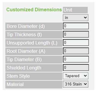
If you do not have an Ashcroft part number but you know your thermowell dimensions, then you can manually enter them. These dimensional fields can be modified when necessary.
Figure 3. Example of where to enter thermowell dimensions manually.
Once the process information and dimensional details are complete, you will need to understand the results.
Understanding your thermowell wake frequency results
There are four types of stresses the calculator will run through to determine the probability of failure:
- Oscillating Stress: This includes the drag and lift forces that cause oscillation. It’s also known as dynamic stress. The thermowell fails if this stress exceeds the fatigue stress limit for the thermowell.
- Steady State Stress: The steady-state stress should not exceed the allowable stress of the thermowell. The allowable stress is determined using Von Mises criteria within the formula of the calculator to calculate whether the stress combinations at a given point will cause failure.
- Pressure: The pressure applied should not exceed the pressure ratings of the thermowell or it will result in a failure.
- Frequency: The resonance frequency of the thermowell must be high enough to prevent destructive oscillations caused by the flow. Most failures are seen in this area when the process conditions allow the thermowell to vibrate to the point of failure.
A thermowell must pass all four of these parameters to be considered adequate for use.
Passing the wake frequency test parameters
Let’s say you've entered all your data and clicked the calculate button but your selected thermowell failed for its intended application. Specifically, it failed both the oscillating stress and the frequency. What now? Take one of these steps:
- Shorten the U dimension. This is the most typical step to correct this failure and is always the best solution if it’s possible in your application.
- Fatten up the shank. In cases when shortening the U dimension is not an option, you can try this approach.
- Run the test with a stronger material. As a final option, you can also try this.
Keep in mind, if you decide to thicken up your root and tip dimensions, remember where you are inserting your thermowell. You do not want to thicken it up so much that your well no longer fits into your nozzle or tee.
Ready to learn more?
Now that you understand the process of calculating wake frequency, you should be better prepared to select the best thermowell for your process. You can always contact a product expert if you have questions about our Wake Frequency Calculator.
For more information on temperature instruments, check out our past articles:
- How Much Do Thermowells Cost? 5 Factors that Influence Price
- Fitting a Thermowell to Bimetal Thermometer or RTDs/Thermocouples
- When Should I Use a Coated Thermowell?
- How Much Do Industrial Bimetal Thermometers Cost?
- How Much Do Temperature Sensors Cost?
Learn more about selecting thermowells by watching our helpful webinar:

Topics:


