
By:
Eric Deoliveira
Business Development Leader
Published on:
March 26th, 2025
Last updated on:
March 4th, 2026
Topics:
Subscribe now and get the latest blog posts delivered straight to your inbox.
By:
Eric Deoliveira
Business Development Leader
Published on:
March 26th, 2025
Last updated on:
March 4th, 2026
Topics:

Hydraulic pressure gauges must be designed to handle pressure spikes, temperature extremes, vibration, material compatibility challenges and mounting requirements common in hydraulic systems.
Managing hydraulic systems in mobile construction equipment, fuel pumps, industrial machinery and automotive braking systems require careful pressure control. Because hydraulic systems use incompressible fluids to generate force, improper pressure management can lead to reduced performance, equipment damage or physical injury.
With extensive experience in pressure measurement for demanding applications, Ashcroft has seen how selecting the wrong gauge can impact safety, accuracy and uptime. Read this article to learn the five most important hydraulic pressure gauge features to evaluate so you can confidently select the right instrument for your application.
1. Resistance to pressure spikes
Resistance to pressure spikes is critical because hydraulic systems can experience sudden surges that reach several times normal operating pressure. In applications such as construction loaders traveling over uneven terrain, or trucks towing heavy loads, unexpected shock can rapidly increase system pressure by tens of thousands of psi. A temporary malfunction or slip within the system can also create a significant surge.
Unlike air, hydraulic fluid cannot be compressed. As a result, pressure spikes can increase four to five times above normal operating pressure. If a pressure gauge is not designed to handle this fluctuation, accuracy can suffer and internal components may be permanently damaged.
When evaluating pressure gauges for hydraulic applications:
- Review maximum pressure capacity
- Compare available pressure ranges in the manufacturer’s datasheet
- Confirm the gauge can tolerate expected surge conditions
Selecting a gauge with appropriate overpressure capability helps protect both the instrument and the system.
2. Ability to withstand temperature extremes
The ability to withstand temperature extremes is essential because temperature changes directly influence pressure measurement accuracy.
Hydraulic systems are often used in unpredictable or harsh environments, such as offshore equipment operating near the ocean floor or construction machinery in sub-zero climates. These systems also generate heat during operation due to the force required to move hydraulic fluid. Because temperature and pressure are closely related, changes in ambient or process temperature can cause shifts in indicated pressure.
When comparing hydraulic pressure gauges:
- Verify the application temperature parameters
- Review the expected offset across the operating temperature range
- Consider whether a dry gauge or liquid-filled gauge is more appropriate
Dry gauges can typically operate at higher temperatures while liquid-filled gauges provide vibration damping but may have different ambient limits. See the chart below for an example of the temperature limits for dry glycerin-filled and silicone-filled versions of the Ashcroft® 8008S Pressure Gauge.
Figure 1. Ashcroft® 8008S Pressure Gauge Temperature Ranges
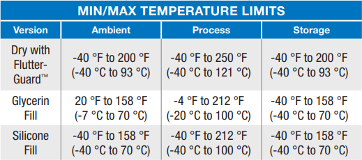
Understanding temperature limits helps maintain measurement accuracy across real-world operating conditions.

3. Protection from flutter and vibration
Protection from flutter and vibration is necessary because consistent pulsation can make gauges difficult to read and shorten instrument life. Pointer flutter occurs when vibration or pressure pulsation causes the indicator to move rapidly back and forth within a small section of the dial. This movement makes it harder for operators to interpret readings.
Flutter can result from:
- System pulsation
- Loose connections
- Environmental vibration
- Changes in surrounding air pressure or temperature
Some degree of flutter does not automatically indicate system failure. However, if the pointer moves more than five percent across the full-scale, steps should be taken to address the root cause or improve damping.
Hydraulic pressure gauges may incorporate:
- Liquid-filled cases
- Internal damping mechanisms
- Movement enhancements designed to reduce oscillation
These features can improve readability, protect internal components and extend service life in high-vibration installations.
4. Assembly and composition
Assembly and composition matter because material selection and construction directly affect durability, safety and compatibility. A hydraulic pressure gauge consists of several key components including:
- The bourdon tube, which is the C-shaped or helical sensing element that converts pressure into mechanical displacement
- The external casing, which protects the internal mechanism from physical damage
- Sealing components, such as gaskets and O-rings that maintain a leak-tight system
Material quality determines how well the gauge withstands internal pressure, external shock, moisture and corrosive conditions. Stainless steel is commonly selected for casing construction because it offers strength corrosion resistance and durability under demanding conditions.
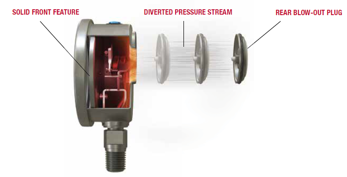
Solid-front versus open-front design is another important consideration.
When a gauge is pushed beyond its limits, rupture is possible. A solid-front gauge incorporates a rear blow-out plug that directs force and debris away from the operator. In contrast, an open-front gauge may expose personnel or equipment to greater risk during an overpressure event.
The solid-front construction example shown below highlights how this design improves operator safety.
Figure 2. Solid-front gauge construction
Selecting appropriate materials and construction features improves both safety and longevity.
5. Compatible mounting options
Compatible mounting options are important because hydraulic systems require flexibility in installation, configuration and connection type. While many gauges are direct mounted onto piping, some applications require panel mounting, flange mounting or other specialized configurations. Certain mounting styles may also require additional hardware or accessories.
In the United States, pressure gauge connections typically follow National Pipe Thread (NPT) standards.
-
Dial sizes from 1.5 to 3.5 inches commonly use 1/8 NPT to 1/4 NPT connections
-
Dial sizes 4.5 inches and larger commonly use 1/4 NPT to 1/2 NPT connections
Ensuring connection size, mounting style and mechanical fit align with system requirements prevents installation issues and measurement errors.
Examples of hydraulic pressure gauges designed for these conditions
Hydraulic systems require gauges built to manage pressure, temperature, vibration, material compatibility and installation demands.
Examples such as the Ashcroft® 8008S Pressure Gauge with a crimped tamper-resistant ring and the Ashcroft® 8009S Pressure Gauge with a removable bayonet ring illustrate two approaches to balancing durability and service access. Both are constructed from 316L stainless steel with laser-welded components and can be configured with solid-front construction for additional safety. Plus, they meet EN837-1 and ASME B40.100 specifications and are CE and RoHS certified for international use.
These examples demonstrate how proper design and construction address the five core requirements discussed above.
Ready to learn more?
Selecting a hydraulic pressure gauge involves more than choosing a dial and connection size. Understanding these common challenges and how to address them helps ensure long-term reliability and safety.
If you want more information, check out the resources below, or contact us to speak to a product expert. In the meantime, download our guide to learn how to avoid common mistakes when choosing the right gauge for your application. 


