
By:
Todd McPadden
Product Sales Leader, High Pressure Transducers
Published on:
March 25th, 2024
Last updated on:
June 17th, 2026
Topics:
Subscribe now and get the latest blog posts delivered straight to your inbox.
By:
Todd McPadden
Product Sales Leader, High Pressure Transducers
Published on:
March 25th, 2024
Last updated on:
June 17th, 2026
Topics:

Chemical vapor deposition (CVD) is a process used to create highly advanced, field-proven thin-film technology for pressure sensors used in mid- to high-pressure applications. These sensors are designed to deliver consistently accurate, reliable and repeatable pressure measurements under some of the most difficult operating conditions.
If you are an Original Equipment Manufacturer (OEM), you know your operations are among the most demanding in any industry. As such, you require instrumentation that can maintain accuracy while withstanding shock, vibration, temperature extremes and high cycle demands.
As a recognized leader in pressure and temperature instrumentation, Ashcroft offers pressure transducers designed to meet these challenges. Our CVD-based sensors are produced in Japan by our parent company, Nagano Keiki, and are incorporated into many of our pressure sensors designed for OEM applications.
In this article, you will learn how CVD technology works in the manufacturing process, where it is used and the benefits it provides to OEM manufacturers and others who rely on accurate pressure measurement. You will also find additional resources to help you learn more about the pressure instruments that incorporate CVD technology and the applications where they excel.
How is CVD technology used to manufacture pressure sensors?
CVD technology manufactures pressure sensors by building them in separate, precise stages that bond polysilicon strain gauges directly onto a stainless-steel diaphragm using thin-film deposition.
The process works as follows:
-
A layer of silicon dioxide is placed over a stainless-steel diaphragm to act as an insulator.
-
A poly-silicon strain gauge is applied over the insulator.
-
A lithography process removes specified areas of the strain gauge, leaving only the areas of the diaphragm that will be measured for changes in resistance.
-
The poly-silicon strain gauges are connected using gold interconnects to form a Wheatstone Bridge circuit. This circuit is then connected to the electronics using wire-bonding techniques commonly used in microelectronics.
-
A proprietary protective layer is applied as a micro-coating over the strain gauge.
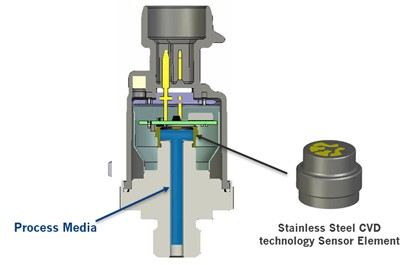
The sensing element is made entirely of stainless steel, allowing it to be welded directly to pressure fittings to create a secure seal.
Figure 1: Transducer with CVD Sensor
How does a CVD pressure sensor work?
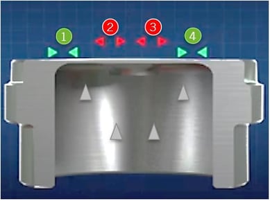
A CVD pressure sensor works by detecting changes in electrical resistance across four polysilicon strain gauges as applied pressure causes a stainless-steel diaphragm to deflect. The electronic circuit is used for calibration and compensation to produce an accurate output.
Here's how the sensor operates:
-
Changes in pressure cause the diaphragm to deflect upward.
-
This creates a change in the resistance of the four strain gauges.
-
As pressure is applied and the diaphragm deflects upward, strain gauges 2 and 3 are placed in tension while strain gauges 1 and 4 are placed in compression.
-
With no pressure applied, the bridge circuit is balanced and the output is zero.
-
Strain gauges in compression experience a decrease in resistance proportional to the applied pressure.
-
Strain gauges in tension experience an increase in resistance proportional to the applied pressure.
Watch the video for an animated view of the process.
Figure 2: CVD Sensor Strain Gauge Tension and Compression
What outputs can CVD pressure transducers provide?
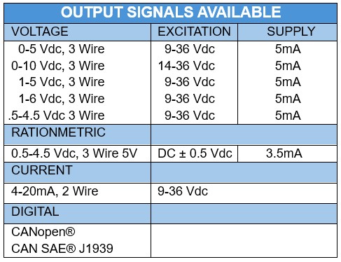
CVD sensor-based transducers can provide multiple outputs, including voltage, ratiometric and current, making them a strong choice for high-precision monitoring.
Figure 3: CVD Pressure Transducer Outputs
This technology is also ideal for the following pressure ranges.
Figure 4: CVD Pressure Ranges

Why is using pressure sensors with CVD technology important in OEM applications?
Pressure sensors with CVD technology are important in OEM applications because they deliver superior accuracy, repeatability, durability and cycle life under the extreme shock, vibration and temperature conditions that OEM environments demand.
There are many reasons why OEMs and others rely on electronic sensors with CVD technology to measure and monitor pressure in their systems.
-
Accuracy. Field-proven polysilicon thin-film sensor technology helps ensure measurement performance that meets application requirements.
- Repeatability. Provides consistent readings over time without requiring span adjustments.
- High cycle life. Designed to withstand millions of pressure cycles.
- Durability. Rugged construction helps protect against shock, vibration, pressure spikes and pulsation common in OEM applications.
- Temperature resistance. Welded construction supports operation in temperatures ranging from -40 to 125 °C.
- All-stainless wetted construction. CVD-based sensors are constructed without glues, epoxies or O-rings, eliminating concerns related to leakage, contamination or silicone fill migration.
Where does CVD technology excel?
CVD technology excels in demanding industrial and mobile applications that require high vibration resistance, long cycle life and wide temperature tolerance.
These applications include:
-
Mobile hydraulics. Requires shock and vibration resistance, high cycle life and wide operating temperature ranges.
-
Lift and load systems. Requires repeatability and long service life.
-
Performance racing. Requires superior vibration resistance and high cycle life.
-
Pump control systems. Requires high cycle life.
-
Compressor systems. Requires vibration resistance and long-term durability.
-
Forestry and mining equipment. Requires exceptional resistance to harsh vibration conditions.
-
Railway applications. Requires high vibration resistance, long cycle life and excellent repeatability.
-
Irrigation systems. Requires temperature resistance and may benefit from freeze-protection options available with all-stainless wetted designs.
Which Ashcroft transducers are built with CVD technology for OEM applications?
Ashcroft offers five CVD-based pressure transducers designed for OEM applications, each engineered to handle specific environmental and performance requirements.
-
S1 High-Volume Sensor. Compact and highly configurable with a broad selection of materials and process connections. Designed for vibration resistance, shock resistance and long cycle life.
-
G2 Rugged-Duty Sensor. Engineered for demanding installations that experience significant vibration, shock and high-cycle operation.
-
GV High-Vibration Sensor. Designed specifically for harsh environments where vibration resistance is critical.
-
KD41 Digital Pressure Transducer. Provides digital outputs including CANopen and J1939 for demanding OEM applications.
-
KM41 Configurable Pressure Transducer. Designed to meet the specific requirements of mobile hydraulics, pneumatics, industrial equipment and automation applications.
Ready to learn more?
Now you know the benefits of CVD technology and the sensors that provide accurate, reliable and repeatable pressure measurements in challenging conditions.
If you want to deepen your knowledge, explore the related resources below or contact us with any questions.
In the meantime, check out our e-guide, 5 Mistakes OEMs and System Integrators Make When Selecting Pressure Transducers.
Topics:


