
Subscribe now and get the latest blog posts delivered straight to your inbox.

Temperature can be measured with a variety of methods. Glass thermometers, resistance temperature devices (RTDs), bimetal instruments, gas expansion (gas-actuated) thermometers and infrared radiation, to name a few. Each offers a unique set of advantages for specific applications.
Another extremely common temperature measurement device is the thermocouple. Its simple design makes it remarkably versatile, reliable and cost-effective. But how does a thermocouple work?
This article will describe the function of thermocouples, the different types and their material composition.
What is a Thermocouple?
A thermocouple is comprised of two wires of dissimilar metals (for example, in a J type thermocouple, one wire is iron, and the other is copper-nickel). These wires are joined at one end, usually by a weld or twist. This joint (junction) must come in contact with the temperature source to be measured.
In some installations, the surface of the twisted or welded wires is all that is needed for contact. In others, the wires are embedded in the sheath of a rigid or flexible probe. This protects the device and allows for easier installation, especially when inserted into a thermowell.
How Thermocouples Work.
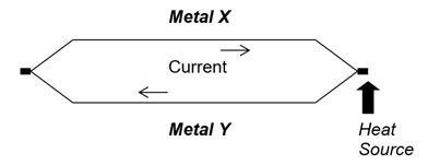
When the two dissimilar wires are joined together at both ends and temperature is applied to one of the junctions, a continuous electrical current will flow through the loop formed by the two wires, producing a measurable voltage.
As the temperature of the source varies, so will the voltage. This phenomenon is referred to as a “thermoelectric circuit,” and the resulting voltage is referred to as the “Seebeck Voltage” (named after Thomas Seebeck, who made the discovery in 1821). The voltage level is a function of the junction temperature and the composition of the two metals. As a result, the changes in the Seebeck voltage are linearly proportional to the changes in the junction temperature.
Figure 1: Thermoelectric Circuit
The Thermocouple Circuit
To apply the thermoelectric circuit pictured above to an actual temperature measurement, we must now break the circuit and add a device to measure the Seebeck voltage.
Figure 2: Thermocouple Circuit
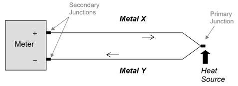
By joining the ends of each wire to the terminals of a voltage meter, we are now creating two new “secondary” junctions in the circuit. Junctions of like materials do not present a problem in a thermoelectric circuit; the current will flow undisturbed, with no effect upon the Seebeck voltage.
However, when a thermocouple wire is connected to a dissimilar metal, an additional voltage (referred to as an “electromotive force” or “EMF”) will be created at the junction, which will work in opposition to the Seebeck voltage. This will distort the resulting temperature measurement. To utilize the Seebeck voltage to calculate the measured temperature, it will be necessary to overcome the effect of the EMF created at these junctions.
Let’s take a look at the eight most common thermocouple types and the materials that comprise them:
Figure 3: Types of Thermocouples
| Type | Materials |
| J | Iron & Copper-Nickel (Constantan) |
| K | Nickel-Chromium & Nickel-Aluminum |
| T | Copper & Copper-Nickel (Constantan) |
| E | Nickel-Chromium & Copper-Nickel (Constantan) |
| R | Platinum- 13% Rhodium & Platinum |
| S | Platinum-10% Rhodium & Platinum |
| B | Platinum-30% Rhodium & Platinum-6% Rhodium |
| N | Nickel-Chromium-Silicon & Nickel-Silicon-Magnesium |
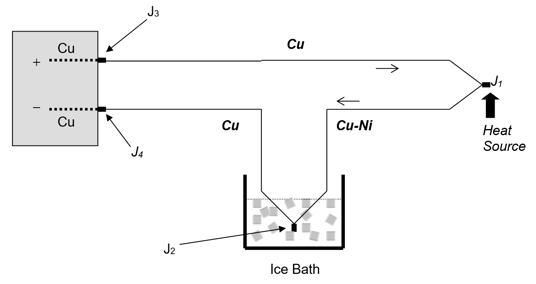
The next example is a type T copper and copper-nickel (constantan) thermocouple. Since most voltage meters utilize copper terminals and internal wiring, the (secondary) junction of the copper side of the thermocouple to the meter (J3) will not generate EMF (opposing voltage) and thus will not compromise the Seebeck voltage.
However, the joining of copper and copper-nickel (J2) will produce EMF, which must be accounted for in the calculations used to derive a temperature reading from the measured Seebeck voltage. One of the values necessary to quantify the EMF is the temperature at the secondary junction (J2).
Reference Junction
Since the purpose of the thermocouple is to measure temperature at the primary junction (J1), leaving the J2 exposed to a different temperature will alter the voltage. Therefore, J2 will need to be controlled to a known consistent temperature to stabilize the equation.
The easiest way to create this constant temperature is by submerging J2 in an ice bath, which creates an environment of 0 °C. We can now use 0 °C as the known temperature of J2, and easily calculate the measured temperature of J1 from the Seebeck voltage. The insertion of J2 into the 0 °C ice bath is referred to as the reference junction.
Figure 4: Reference Junction of Thermocouple Circuit
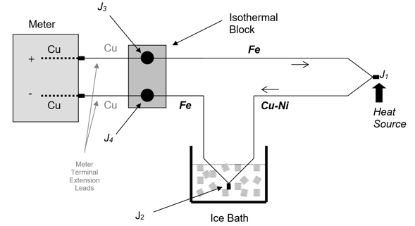
For other types of thermocouples where copper is not one of the two metals (such as a J type, as illustrated below), a third junction of dissimilar metals will be formed. To limit the error caused by the additional junction, an “isothermal block” (good heat conductor with low electrical conductivity) is added to the circuit to equalize the temperature across the two junctions.
With the isothermal block in place, the EMF (voltage) created at the J3 copper-to-iron junction will act in opposition to the EMF (voltage) created at the J4 copper-to-iron junction, thus neutralizing the EMF caused by the joining of these dissimilar metals at these two points.
Figure 5: Isothermal Block of Thermocouple Circuit
“Automatic” or “Internal” Reference Junction
Although the use of an ice bath reference results in the most accurate temperature measurements, the ice bath is often impractical, especially in portable applications. Thus, some other means must be employed to measure or control the EMF caused by the joining of the two dissimilar thermocouple metals at J2.
Most temperature instruments (transmitters and meters) use an internal circuit to accomplish this reference. This is referred to as “cold junction compensation” (CJC). The CJC circuitry measures the junction temperature at the inlet of the instrument and then adds a correction factor for 0°C. This allows the instrument to display the correct temperature of J1.
Thermocouple Shapes and Sizes
While the basis for thermocouples is just two wires, they can be incorporated into many different style instruments to suit specific installations. In some cases, they are permanently installed deep within a reactor or other harsh industrial environments, while in other applications they may be attached to a portable device for spot testing.
Here are some examples of Ashcroft thermocouple devices:
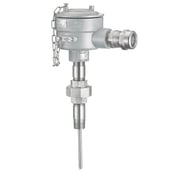
S50 Industrial probe for installation in a thermowell
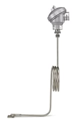
S70 Industrial probe with thermocouple pad welded to the contact surface
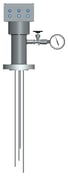
Heavy industrial “multi-point” probe with several thermocouple probes
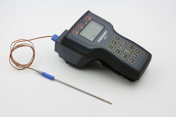
ATE-2 portable calibrator with thermocouple interface and probe
We don’t like to pressure you, but we have more information.
Now that you better understand how a thermocouple functions and the benefits it can offer, you can choose the best solution for your application.
For more information on temperature instruments, read some of our related articles:
- When to Use an RTD vs. a Thermocouple Temperature Sensor
- Product Review: New RTDs and Thermocouples
- Fitting a Thermowell to Bimetal Thermometers or RTDs/Thermocouples
- How Much Do Temperature Sensors Cost?
Feel free to reach out to our specialists here at Ashcroft to answer all of your temperature measurement questions!
Topics:


