
Subscribe now and get the latest blog posts delivered straight to your inbox.

This article was originally published on October 30, 2023, by Rick Zarafin and was updated by Dave Dlugos.
In the article “Why and When is RTD Calibration Necessary?”, we explored how Resistance Temperature Detectors (RTDs), such as our S81 and S50 models, offer superior performance over thermocouples for temperature process measurements due to their high accuracy and repeatability. RTDs are particularly suitable for critical applications, including chemical and refining processes, where precise temperature measurements are essential.
To fully grasp the importance of RTD calibration, it is crucial to understand the fundamental working principles of an RTD. As a leader in temperature and pressure instrument solutions, Ashcroft creates articles to address common questions from our customers. Our goal is to provide you with the information and tools you need to make informed decisions about your temperature measurement solutions.
In this article, you'll learn how RTDs work, gain knowledge about the different levels of accuracy achievable with RTDs, and see how to maintain and calibrate these devices to meet your specific needs. You will also receive links to additional resources to help deepen your understanding of these temperature measurement instruments.
How do RTD temperature instruments work?
The resistance of an RTD rises consistently and predictably as temperature increases. This characteristic is advantageous because it ensures repeatability via the RTD's temperature coefficient, establishing a linear correlation between resistance and temperature. This allows customers to configure process control systems that accurately regulate control valves, heaters, pumps, and other essential equipment based on precise temperature measurements.
4 Steps for Configuring an RTD Element Within the Probe
Configuring an RTD element inside a probe is a methodical process that ensures optimal performance and accuracy. Here’s how you do it:
- Select platinum for resistance material: Begin by choosing platinum, known for its stable and predictable resistance properties, as the core material.
- Measure the resistance signal: Use a transmitter, PLC, or DCS to accurately measure the resistance signal. At 0°C, a well-calibrated RTD will exhibit a precise resistance of 100.0 Ω.
- Determine the tolerance class: Identify and select the appropriate tolerance class based on your specific application requirements. This choice will influence the accuracy and reliability of your RTD.\
- Choose temperature range and construction type: Based on the selected tolerance class and element style, decide on the temperature range and construction type. This ensures the RTD can withstand the operational environment and deliver consistent performance.
See the chart below for detailed information on temperature ranges corresponding to Class B tolerance and thin film element style.
Figure 1: RTD Calibration Process.
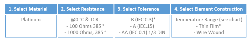
Figure 2: RTD, Resistance to Temperature Relationship.
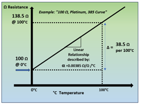
Figure 3: RTD Element Type, Tolerance and Temperature Range.
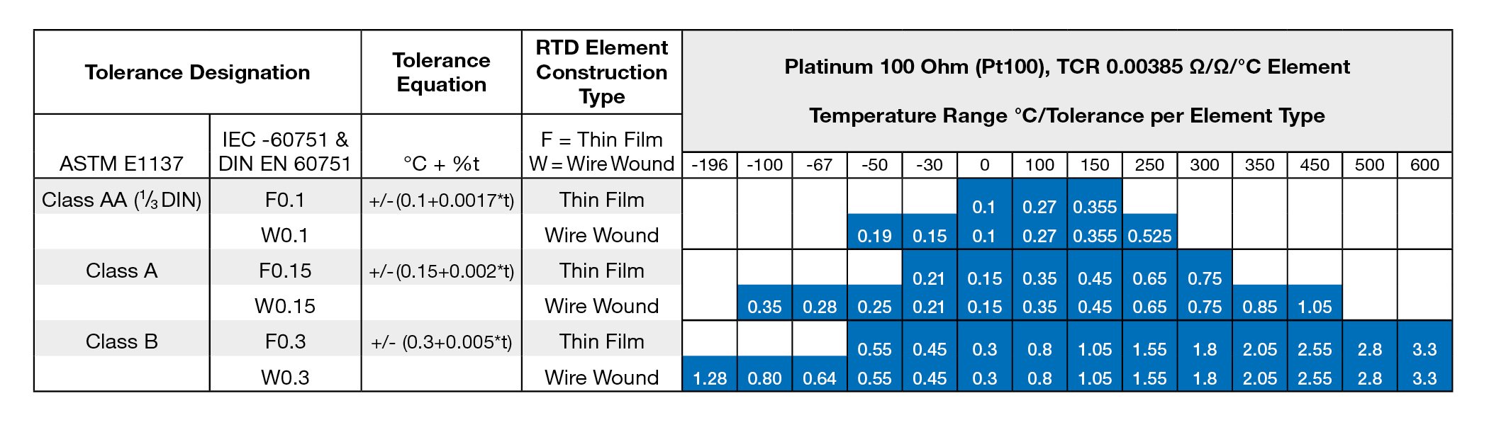
Note: Operating the RTD Element above the specified maximum temperature range may stress the sensor and lead to aging effects. Stressing the sensor can lead to deviation within the specified range and affect performance.
How RTD calibrations are performed.
For new EPC installations or critical applications, it is imperative to ensure that temperature measurements adhere to stringent accuracy specifications. Conducting calibration, accompanied by a certified Calibration Report, is the most reliable method to validate sensor precision and provide correction factors that enhance process measurement accuracy.
Comparison RTD calibration process
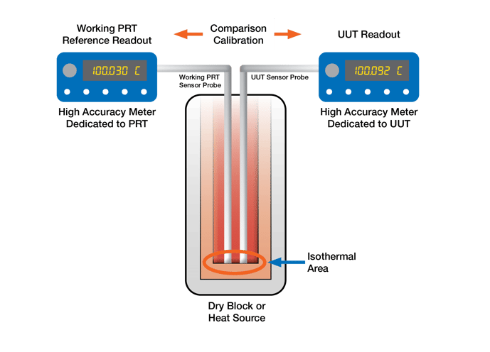
The most commonly used method for calibrating RTDs is comparison calibration which is typically executed by laboratory engineers and technicians. With this approach, RTDs are calibrated against a high-accuracy reference sensor, usually a Platinum Resistance Thermometer (PRT).
The primary function of the PRT is to ensure the precision of multiple sensors destined for plant installations. These PRTs are certified by accredited laboratories under ISO 17025 standards and are traceable to international standards such as ITS-90 through national laboratories like NIST.
Figure 4: Traceable Link to National Institutes and International Standards.
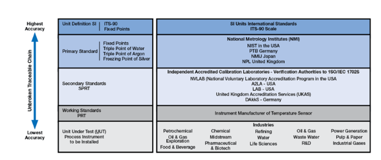
The PRT itself is calibrated using either a “Standard” PRT or a “Primary” PRT. In the illustration below, high-accuracy meters are used to take readings from both the PRT and the RTD that will be installed in the plant. In the Calibration Report, the RTD to be installed is referred to as the UUT (Unit Under Test). Other commonly used terms are SUT (Sensor Under Test) and DUT (Device Under Test).
Figure 5: Comparison Calibration Example.
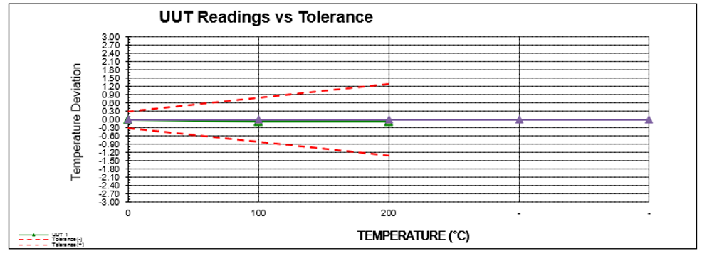
RTDs can be calibrated at temperature points specified by the customer or at preset points defined by the sensor manufacturer. Calibration certificates accompany the results, detailing all relevant test equipment and reference sensors utilized during the calibration process.
Figure 6: Ashcroft Sample Certified RTD Calibration Chart.
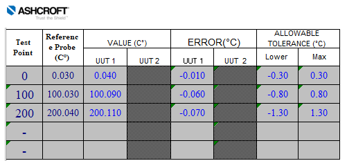
The Calibration report will indicate the error for the test sensor (UUT, Unit Under Test) at each temperature point as compared to the measurement of the reference PRT sensor.
Figure 6: Sample Error Readings in Calibration Report.
Recommended RTD temperature sensor calibration intervals.
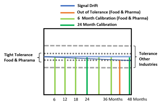
RTDs experience minimal drift compared to thermocouples due to their construction and operational temperature ranges. They are preferred in high-accuracy applications like high vibration, severe temperature cycling, and Safety Shut Down Systems with SIL requirements because they typically fail open, unlike thermocouples, which may produce undetected faulty signals.
RTDs are widely used in regulated industries requiring calibration. The recalibration frequency depends on the application, with high-tolerance sectors like food and pharma needing more frequent calibration to maintain efficiency.
Figure 7: Application Process Tolerances
Next steps regarding RTD calibration.
Now that you know how RTD calibrations are performed, you can research the solution that best suits your application. Keeping these factors in mind can help ensure you avoid problems and keep your process running safely and reliably.
We understand that every situation is different. That’s why you can trust us to guide you through every step of your instrument selection and application needs, including MRO and turnarounds, working with engineering procurement construction (EPC), and corporate engineering firms on large capital projects with a dedicated support team.
If you want to learn more about RTDs and other temperature sensors, check out some of our other blog posts:
- When to Use an RTD vs. Thermocouple
- Product Review: New RTDs and Thermocouples
- Fitting a Thermowell to Bimetal Thermometers or RTDs/Thermocouples
- How Much Do Temperature Sensors Cost?
Or reach out to one of our product experts with questions.


