
Subscribe now and get the latest blog posts delivered straight to your inbox.

This article was originally published on October 23, 2023, by Rick Zarafin and updated on August 19, 2024 by Dave Dlugos.
As an industrial instrument designer, you are faced with a multitude of temperature measurement options to choose from. In addition to the commonly used infrared, bi-metal, gas-actuated thermometers and thermistors, to name a few. Each of these options stands out as a reliable choice for industrial automation and process applications.
However, the instruments predominantly selected for industrial automation and process applications are thermocouples and Resistance Temperature Detectors (RTDs) because of their proven ability to provide accurate and reliable readings. Each of these sensors has unique advantages and can be configured to match the application needs for optimum service life and performance.
Based on my experience working with instrumentation and reliability teams, I’ve seen and compared the benefits of both options. Thermocouples, for example, are often chosen for a robust signal, cost-effective price and ability to withstand most process plant specifications, including harsh vibration and high-temperature range up to 2300° C. RTDs, on the other hand, are the top choice for applications demanding higher accuracy levels and minimal drift.
In this article, you will learn about the advantages of RTDs and the significance of RTD calibration in ensuring precise and consistent readings for an extended lifespan. You will also be directed to additional resources to help deepen your knowledge about these instruments and their applications.
RTDs are more accurate than thermocouples.
RTDs offer precise and consistent temperature measurements across a wide range from -196° C to 600° C. Unlike thermocouples, RTDs do not need cold junction compensation or compensated alloy lead wire for temperature measurement, making them a reliable choice for demanding applications.
Common applications for RTDs.
The following applications rely on RTDs for the instrument’s high accuracy in repeatable process variable measurements.
• Clean In Place (CIP)
• Pharmaceutical
• Chemical and Refining Processes
• Cryogenic
• Custody Transfer
• Critical Control Loops
• Safety Shut Down Systems
• Asset Protection
• Compressor Efficiency Monitoring
Expected tolerances for RTD elements.
Thin Film and Wire Wound elements are the two types of configurations categorized by ASTM and IEC 60751 into Tolerance Class A, Class B, and Class AA. IEC Tolerance Designations outline the element construction, with Class AA designated as W0.1 for Wire Wound and F0.1 for Thin Film.
The following chart provides an overview of the expected tolerances for commonly used RTD elements in temperature measurement, focusing on the 100 Ohm Platinum sensing element with a 0.00385 Temperature Coefficient.
Figure 1: Expected tolerances for RTD elements.
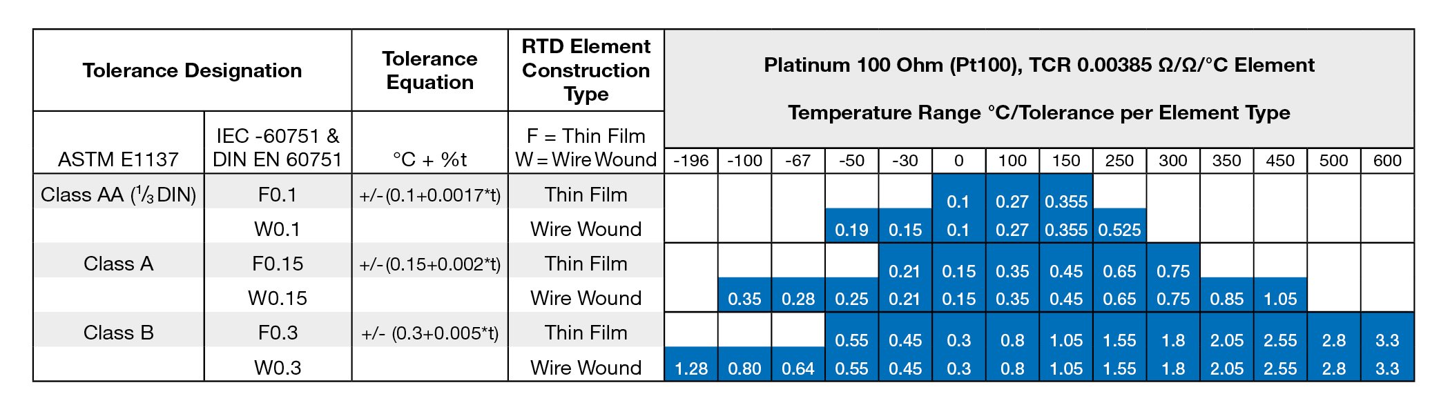
Note: Operating the RTD Element above the specified maximum temperature range may stress the sensor and lead to aging effects. Stressing the sensor can lead to deviation within the specified range and affect performance.
Each type of RTD element and its corresponding accuracy class are constrained by specific temperature ranges, as illustrated in the chart. While Class AA boasts the highest precision within this category, Class B in a Wire Wound configuration offers the most extensive temperature range. Although RTD elements can measure temperatures exceeding these ranges, up to 850°C, pushing the element beyond its designated limit may result in aging effects and impact sensor performance.
Why calibrate an RTD?
While RTDs typically offer high accuracy levels without the need for calibration, there are instances where it may be beneficial to ensure they are performing within specified tolerances. Here are four scenarios where calibration could provide significant advantages:
1. Enhancements in chemical, refining, power, process, and automation industries.
Process Engineers and Safety Teams must closely monitor chemical reactions to prevent temperature spikes. They analyze temperature differentials in real time to identify abnormal conditions and take preventive measures like emergency shutdowns.
Calibration provides error data for RTD elements, helping process engineers reduce measurement uncertainty. Operation teams can use these calibration reports to adjust sensors for safety and process efficiency improvement.
Applications requiring precise temperature detection can benefit from a specialized calibration process known as Callendar Van Dusen (CvD), which calculates the resistance-to-temperature relationship for each element using calibration-generated coefficients.
2. Industry and plant requirements
Industries with stringent temperature requirements, such as pharmaceuticals, life sciences, and Clean in Place (CIP), must ensure that all production instrumentation is properly calibrated. CIP pasteurization units need to maintain precise temperature differentials between inlet and outlet temperatures for successful operation. Calibrated RTDs offer the necessary accuracy for these units and validate temperature measurements as required.
In addition to adhering to company, corporate, and local plant standards, regulatory agencies like the FDA may require or recommend recalibration schedules based on predetermined timelines or data-driven schedules.
3. Engineering procurement construction (EPC) projects
EPC construction projects mandate the calibration of most new instruments. Here are a few reasons why this is important:
-
Calibration offers a verifiable confirmation that instruments align with specifications, ensuring precision and accuracy in temperature measurements.
-
Inspection teams rely on documented evidence to affirm the RTDs' adherence to specified accuracy levels as outlined in the instrument data sheet.
-
New instrument installations serve as a benchmark for anticipated outcomes, providing end-users with comprehensive documentation, including calibration reports, before start-up and commissioning.
-
Project Documentation Requirements (PDR) mandate the inclusion of calibration reports in a controlled and auditable process, fostering a safe operational environment for process and automation plants.
Health Safety Environment (HSE) engineers who take over plant unit operations may also use data from calibration reports to establish expected unit performance for various equipment including compressors, turbines and other critical assets. Plus, runtime engineers and maintenance departments can use the data to help investigate process discrepancies and implement corrective and preventive action plans as needed.
4. Quality manufacturing program assurance
According to ASTM and IEC standards, the accuracy specified in the chart pertains solely to the element (Thin Film or Wire Wound). When calibrating a probe, the tolerance error for the entire sensor probe, including the lead wire, will be determined. Any measurement errors introduced during the manufacturing process will be identified and addressed through the calibration process.
Wire Wound and Thin Film elements specifically chosen for industrial applications are securely housed within metal sheaths with mineral insulation, providing an extra layer of protection. The slender platinum wires of these elements, ranging from 0.006” to .008” in diameter, are meticulously welded to significantly larger conductors before being connected to flexible lead wires. To safeguard the electrical signal's precision, the probe is carefully sealed with hermetic potting, ensuring the integrity of the entire sensor assembly.
This intricate process involves numerous meticulous steps, and any misstep can result in errors within the sensor assembly. For instance, a mere 1-ohm increase in resistance during the manufacturing of a platinum RTD could potentially lead to a temperature error as significant as 0.4° C. 
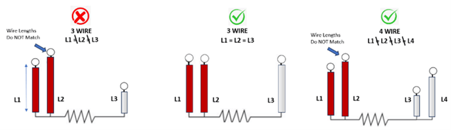
RTD wiring configurations.
RTDs in industrial plants are commonly configured with either a "3-wire" or "4-wire" setup. While the three-wire configuration is more prevalent, it necessitates matching lead wire lengths, unlike the four-wire RTD setup.
In a 3-wire configuration, the electronics within a transmitter, DCS, and PLC may struggle to accommodate any resistance variance in the third lead wire due to unmatched lengths. This discrepancy arises from the assumption that the measured resistance in the second leg mirrors that of the third leg. The calibration procedure will identify such variations and ensure the certification of not just the element but the entire sensor assembly as well.
Figure 2. Wire Configuration Examples.
RTD –calibration traceability.
To prevent unexpected shutdowns and maintain high product quality, the procurement and inspection departments should depend on the Manufacturer’s Quality Programs and Calibration Reports with traceability to the international standard ITS-90 Scale through ISO/IEC 17025 certified labs and equipment.
The chart below illustrates the connection between the installed sensors and the standards employed during the calibration procedure.
Figure 3. An unbreakable traceable chain.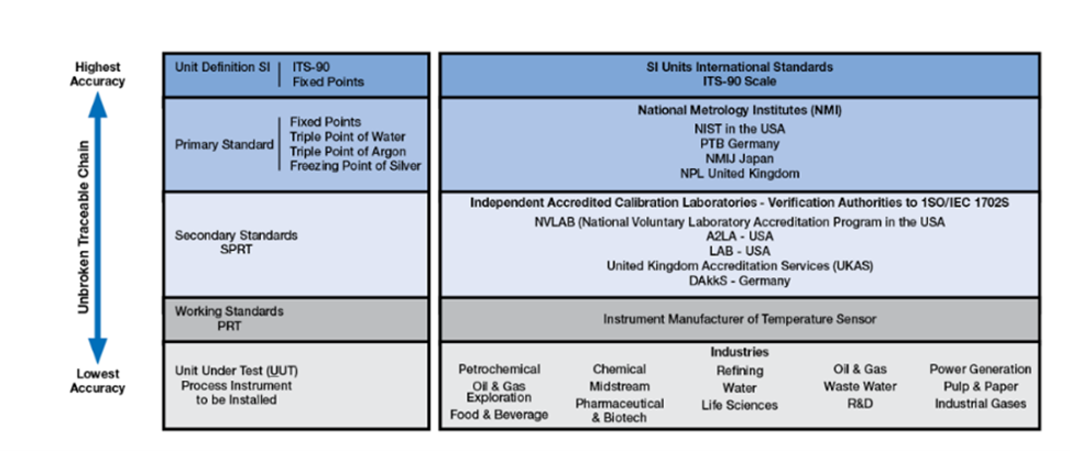
When to recalibrate an RTD.
Recalibration schedules will depend on the application and industry. Unlike thermocouples, RTDs will not experience significant drift and therefore will not typically require a recalibration. For example, the following conditions may stress an RTD and require calibration:
• Operating sensor element above its specified temperature range
• High vibration applications
• Severe temperature cycling
RTDs provide stable and reliable signals when configured correctly. A recalibration can be used to confirm signal integrity and increase confidence in critical temperature measurements.
Final thoughts on RTD calibration benefits.
Now that you know more about why and when RTD Calibration may be necessary, you can research the solution that’s best suited for your application. Keeping these factors in mind can help ensure that you avoid problems and keep your process running with reliable and accurate temperature measurements.
You deserve to feel confident in your measurement equipment. At Ashcroft, we understand that not all applications are the same and requirements can vary. We provide support for your everyday operational needs, maintenance, repair and operations (MRO), working with engineering procurement construction (EPC) and corporate engineering firms on large capital projects with a dedicated support team.
If you want to learn more about RTDs and other temperature sensors, check out some of our other blog posts:
- Product Review: New RTDs and Thermocouples
- Fitting a Thermowell to Bimetal Thermometers or RTD/Thermocouples
- How Much do Temperature Sensors Cost?
Or reach out to one of our product experts with questions. In the meantime, download our guide to learn more about RTD and Thermocouple temperature probes.


