
By:
Todd McPadden
Product Sales Leader, High Pressure Transducers
Published on:
March 2nd, 2026
Topics:
Subscribe now and get the latest blog posts delivered straight to your inbox.
By:
Todd McPadden
Product Sales Leader, High Pressure Transducers
Published on:
March 2nd, 2026
Topics:

Hydraulic systems in mobile construction equipment, agricultural machinery, industrial automation and safety-critical equipment rely on precise pressure feedback to maintain control and protect operators.
Because hydraulic fluid is incompressible, sudden load changes can create extreme pressure impulses. If your pressure sensor cannot tolerate harsh conditions such as pressure spikes, high-cycle fatigue, shock, vibration, temperature extremes and electrical noise, the result may be unstable control loops, premature component failure or unsafe operation.
With decades of experience designing pressure measurement solutions for demanding OEM environments, Ashcroft designs it hydraulic pressure transducers to perform in these conditions. Read this article to learn the five most important features for hydraulic pressure sensors so you can ensure your instrument delivers stable, repeatable electrical output over the long term.
1. Resistance to pressure spikes and high-cycle loading
Resistance to pressure spikes and continuous cycling is essential because hydraulic systems regularly experience impulses that exceed normal operating pressure by four to five times.
Pressure spikes occur when fluid velocity changes rapidly, which is similar to a water hammer effect. These high-magnitude pulses can develop in microseconds and repeatedly stress the sensing diaphragm. Over time, this leads to zero shift, drift or mechanical fatigue if the sensor is not engineered for sustained cycling.
Hydraulic applications frequently involve rapid cycling, abrupt load changes, pump pulsation and continuous high-pressure operation. A transducer must not only survive these conditions but maintain calibration accuracy through them.
When evaluating a hydraulic pressure transducer, review:
-
Cycle life rating (many high-performance models are rated up to 50 million cycles)
-
Overpressure and burst pressure specifications
-
Proper pressure range selection with adequate safety margin
-
The need for protective accessories such as snubbers or throttle screws in extreme impulse environments
A sensor built for sustained high-cycle loading reduces downtime and maintains long-term system reliability.
2. Long-term accuracy and repeatability (Total Error Band)
Long-term accuracy and repeatability are critical because hydraulic control systems depend on stable electrical output to maintain performance and safety. Accuracy describes how close a measurement is to the true pressure value. Repeatability describes how consistently the sensor returns the same output under identical conditions. Repeatability is inherent to the sensing technology and construction. It cannot be corrected through calibration.
Hydraulic environments expose sensors to temperature swings, vibration, high-cycle fatigue and electrical interference. Because of this, evaluating Total Error Band (TEB) is more meaningful than reviewing a single-point accuracy number.
TEB combines several potential sources of inaccuracy, including non-linearity (deviation from an ideal straight-line response), hysteresis (difference in output between increasing and decreasing pressure), non-repeatability (variation when measuring the same pressure multiple times), zero offset error, span setting error and temperature effects across the operating range.
By including these factors, TEB provides a realistic picture of how the sensor will perform in real-world conditions, not just in a laboratory at room temperature.
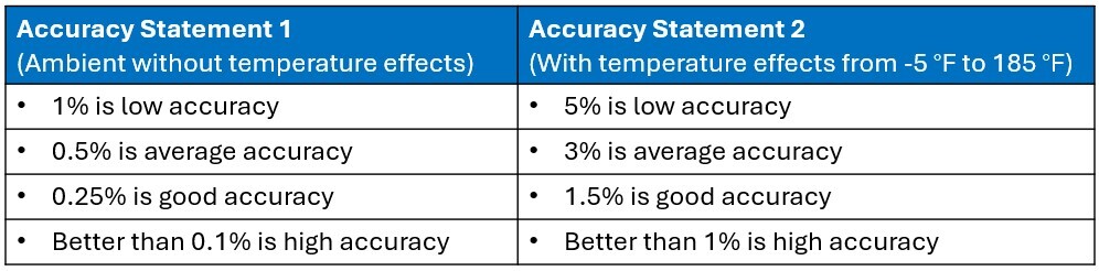
An accuracy statement is the manufacturer’s published specification that defines how much a sensor’s output may deviate from the true pressure value. However, not all accuracy statements include the same performance factors. Some exclude temperature effects or zero and span setting errors, which can significantly impact field performance.
Figure 1: Accuracy statement comparison chart (includes zero and span)
When comparing hydraulic pressure sensors:
-
Ensure temperature effects are included in the accuracy statement
-
Review stability specifications over time (for example, percent of span per year)
-
Confirm repeatability performance for long-term control reliability
Figure 2: OEM pressure sensor elements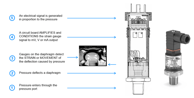
Stable output improves closed-loop control performance and reduces recalibration requirements.
3. Shock and vibration protection
Shock and vibration resistance is essential because mobile hydraulic systems operate in physically demanding environments. Construction equipment, agricultural vehicles and off-highway machinery are routinely exposed to mechanical shock from terrain impact, engine vibration and harmonic pressure waves. These forces can degrade sensor performance if the internal structure is not properly designed.
Vibration may cause wire bond fatigue, signal instability or gradual mechanical degradation of the sensing element. For this reason, the underlying sensing technology and construction method are critical.
Advanced technologies such as stainless steel thin-film Chemical Vapor Deposition (CVD) bond strain gauges directly to a stainless-steel diaphragm, creating a rugged, all-metal sensing structure without adhesives or elastomer seals. This construction improves survivability under shock, vibration and high cycle loading.
Ashcroft pressure transducers, including the S1 OEM Pressure Transducer, G2 Pressure Transducer and S3 Pressure Transducer, all use CVD sensing technology to achieve precise and consistent pressure measuring in higher pressure applications. Watch video to learn more.
Other design features that enhance durability include:
-
Compact sensing element layout to reduce stress concentration
-
Silicone gel protection for delicate internal wire bonds
-
All-welded stainless-steel pressure connections
-
Reduced internal mass to limit mechanical fatigue
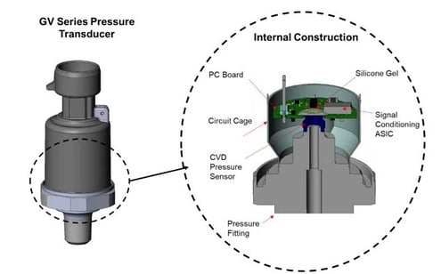
A mechanically robust sensor, like the Ashcroft® GV Pressure Transducer with an internal vibration resistant design maintains stable electrical output even in high-vibration environments.
Figure 3. Ashcroft® GV Pressure Transducer internal construction
4. Temperature and environmental protection
Temperature and environmental resistance are essential because hydraulic equipment often operates in unpredictable and extreme conditions. Hydraulic systems may experience sub-zero startup temperatures, high engine compartment heat, rapid thermal cycling, washdown exposure and contamination from dust or moisture. These conditions affect both the sensing diaphragm and the signal conditioning electronics.
A pressure sensor, like the Ashcroft® S1 OEM Pressure Transducer must maintain accuracy across its full specified operating temperature range, not just at reference temperature.
When evaluating environmental performance, look for:
-
Wide operating temperature range (for example, -40 °F to 257 °F)
-
Clearly defined TEB across temperature extremes
-
Low temperature coefficients for zero and span
-
IP65 or IP67 ingress protection ratings
-
Corrosion-resistant wetted materials such as 304, 316 or 17-4 PH stainless steel
Matching the sensor’s environmental rating to actual field exposure ensures reliable output over the life of the equipment.
5. Electrical integration and signal integrity
Electrical integration and signal integrity are critical because hydraulic pressure transducers provide real-time data to control systems, electrical control units (ECUs) and programmable logic controllers (PLCs). Unlike mechanical gauges, transducers must maintain signal quality in electrically noisy environments such as engine compartments and industrial automation systems. Poor electrical immunity can introduce noise, drift or signal corruption.
Key electrical considerations include:
-
High immunity to EMI/RFI interference
-
Stable signal conditioning and filtering
-
Output options such as 4–20 mA, 0–5 Vdc, 0–10 Vdc or ratiometric
-
Compatibility with ECU-based control systems
-
Configurable electrical connectors to match harness requirements
In OEM hydraulic systems, proper electrical integration ensures accurate communication between the sensor and control architecture, improving responsiveness and system stability.
Ready to learn more?
Selecting a hydraulic pressure transducer involves more than choosing a pressure range and output signal. Understanding how pressure spikes, vibration, temperature extremes and electrical noise influence long-term performance helps ensure safe, stable and efficient hydraulic system operation.
If you would like assistance selecting the right hydraulic pressure sensor for your application, contact us and one of our product experts can assist you. In the meantime, review related resources below, or download our guide to learn the common mistakes OEMs and system integrators make when selecting pressure sensors.


