


Subscribe now and get the latest blog posts delivered straight to your inbox.

Every pressure gauge, RTD, thermocouple, transducer, and thermometer comes with an accuracy spec, but that number only tells part of the story. Accuracy is really a statement of maximum allowable error. How much error you actually see depends on the standard behind the instrument, how the error was calculated, and how the instrument is installed.
Read on to learn how accuracy is defined for the most common pressure and temperature instruments, where hidden error comes from, and how to compare specs on equal footing.
What does accuracy mean for a measuring instrument?
Accuracy is how far a measured value can depart from the accepted standard for that quantity, so it's always expressed as an inaccuracy. A gauge rated ±1% of span can have an error up to 1% of its span.
That "of span" wording matters. On a 0 to 1,000 psi gauge, ±1% of span is ±10 psi whether you're reading 900 psi or 50 psi, so error becomes a much larger share of the reading at the low end. For pressure gauges, the best practice is to size the gauge so normal operation falls near mid-scale.
How is temperature instrument accuracy defined?
Each temperature technology has its own governing standard. For example, dial thermometers are graded as a percent of span, while RTDs and thermocouples are rated by tolerance classes in degrees.
Bimetal and gas actuated thermometers
Bimetal and gas actuated thermometers are graded under ASME B40.200 in North America and EN 13190 in Europe:
- Grade A or Class 1 (±1% of span): Process measurement in chemical plants, power generation, oil and gas, and other applications that need tighter indication.
- Grade B or Class 2 (±2% of span): General purpose indication in HVAC, utility systems, storage tanks, and non-critical monitoring.
RTDs
RTD accuracy is defined by IEC 60751 in three classes, and the tighter the class, the narrower the temperature range.
Figure 1. RTD accuracy classes
| Class | Tolerance | Wire wound range | Thin film range |
|---|---|---|---|
| Class B (good) | ±0.3 °C | -196 to 600 °C (-320 to 1112 °F) | -50 to 500 °C (-58 to 930 °F) |
| Class A (better) | ±0.15 °C | -100 to 450 °C (-148 to 842 °F) | -30 to 300 °C (-22 to 572 °F) |
| Class AA (best) | ±0.1 °C | -50 to 250 °C (-58 to 482 °F) | 0 to 150 °C (32 to 302 °F) |
Lead wire resistance adds its own error, so wiring matters too:
- 2-wire (good): Simplest option, best kept to short cable runs.
- 3-wire (better): Most common for industrial service and transmitter inputs.
- 4-wire (best): Cancels lead resistance entirely, the standard for test and measurement.
Thermocouples
Thermocouple tolerances are set by ASTM E230 as standard and special limits of error, and by IEC 60584-2 as Class 1, 2, and 3.
Figure 2. ASTM E230 Thermocouple types
| Type | Standard limits | Special limits | Common applications |
|---|---|---|---|
| T | ±1 °C | ±0.5 °C | Cryogenics and freezers |
| J | ±2.2 °C | ±1.1 °C | General industrial |
| E | ±1.7 °C | ±1 °C | Higher accuracy general industrial |
| K | ±2.2 °C | ±1.1 °C | Most common, general industrial |
| N | ±2.2 °C | ±1.1 °C | Oxidation resistant, less drift |
| S | ±1.5 °C | ±0.6 °C | High temperature furnaces |
| R | ±1.5 °C | ±0.6 °C | High temperature heat treating, biotech |
| B | ±0.5 °C | ±0.25 °C | Highest temperature |
Figure 3. IEC 60584-2 Thermocouple types
| Type | Class 3 (Good) |
Class 2 (Better) | Class 1 (Best) |
|---|---|---|---|
| T | ±1 °C | ±1 °C | ±0.5 °C |
| J | N/A | ±2.5 °C | ±1.5 °C |
| E | ±2.5 °C | ±2.5 °C | ±1.5 °C |
| K | ±2.5 °C |
±2.5 °C | ±1.5 °C |
| N | ±2.5 °C |
±2.5 °C | ±1.5 °C |
| S | ±1.5 °C | ±1.5 °C | ±1 °C |
| R | N/A | ±1.5 °C | ±1 °C |
| B | N/A | ±0.25 °C | N/A |
Thermocouples also drift, a gradual, permanent shift in output caused by high temperature aging, contamination such as "green rot" in Type K, and mechanical stress from vibration or thermal cycling. Because the change happens inside the alloy, it can't be calibrated out. Possible solutions include:
-
Replace the Sensor: Because metallurgical changes occur inside the pure alloy wires, severe drift cannot be corrected or recalibrated
-
Upgrade Specifications: For high-heat applications, use heavier-duty sheathing (like Inconel) or switch to a more oxidation-resistant sensor type (such as Type N).
-
Check Connections: Ensure your terminal connections are clean, tight, and free of electrical interference or ground loops that mimic drift.he Sensor: Because metallurgical changes occur inside the pure alloy wires, severe drift cannot be corrected or recalibrated
Thermowells and immersion depth
Even the most accurate sensor reads wrong if its sensing area isn't fully in the process. Bimetal and gas actuated thermometers need 2 to 3 inches of immersion, while tip-sensitive RTDs and thermocouples need only about ½ inch.
Choose a thermowell with a U dimension that covers the full sensing area of the instrument. The thermowell shank type also affects the response time. Straight shank wells are the strongest; stepped shank wells have the fastest response time; and tapered shank wells are the most versatile.
How is pressure gauge accuracy graded?
Pressure gauge accuracy is defined by two common standards: ASME B40.100 uses accuracy grades, while EN 837-1 uses accuracy classes. Both express the maximum allowable error as a percentage of the gauge’s span. Some ASME grades allow more error in the lower and upper quarters of the scale than in the middle half. EN 837-1 classes, ranging from 0.1 to 4.0, apply the same error limit across the full scale.
Figure 4. ASME B40.100 Pressure gauge accuracy chart
| ASME B40.100 grade | Accuracy (% of span) | Minimum recommended dial size |
|---|---|---|
| 4A | ±0.1% | 8½ in. |
| 3A | ±0.25% | 4½ in. |
| 2A | ±0.5% | 2½ in. |
| 1A | ±1% | 1½ in. |
| A | ±1% middle half, ±2% upper and lower quarters | 1½ in. |
| B | ±2% middle half, ±3% upper and lower quarters | 1½ in. |
| C | ±3% middle half, ±4% upper and lower quarters | 1½ in. |
| D | ±5% | 1½ in. |
Figure 5. EN 837-1 Pressure gauge accuracy chart
| EN 837-1 Accuracy Classes (± % of Span)(Excluding Friction) | Maximum Friction (%of Span) |
|||
| Accuracy class | Lower 1/4 of Scale |
Middle 1/2 of Scale |
Upper 1/4 of Scale |
|
| 0.1 |  |
0.1 |  |
0.1 |
| 0.25 |  |
0.25 |  |
0.25 |
| 0.6 | |
0.6 |  |
0.6 |
| 1.0 | |
1.0 |  |
1.0 |
| 1.6 | |
1.6 |  |
1.6 |
| 2.5 | |
2.5 |  |
2.5 |
| 4.0 | |
4.0 |  |
4.0 |
Accuracy is only useful if you can read it, so dial size and graduation spacing should match the grade. On dual scale gauges, the dominant scale, typically the inner one, carries the primary graduations.
Ashcroft's 1279 Duragauge® is a 4.5", grade 2A built for readability and high accuracy process indication.
What affects pressure switch accuracy?
For pressure switches, repeatability and deadband matter more than a single accuracy figure. Repeatability is how closely consecutive actuations agree under the same conditions, approaching the setpoint from the same direction.
Deadband is the gap between setpoint and reset. A switch set on rising pressure resets lower, and one set on falling pressure resets higher.
Figure 4. Deadband illustration
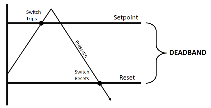
Deadband depends on the pressure range, diaphragm material, and switch element, so check the data sheet to make sure the switch resets where your process needs it to.
Read "What is a Deadband?" for additional details.
How do you read a pressure transducer accuracy statement?
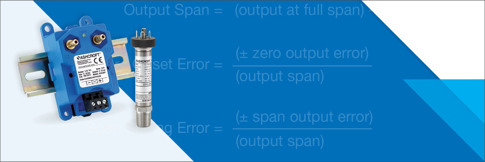
A transducer accuracy statement should include every relevant error source: non-linearity, hysteresis, non-repeatability, zero offset, and span setting error. How those errors are measured and combined can more than double the published accuracy statement for the same sensor.
Terminal point vs. best fit straight line
The terminal point method measures non-linearity against a line drawn through the sensor's actual zero and full scale outputs, so zero and span errors are already included.
Best fit straight line (BFSL) uses the line that minimizes deviation, which produces a smaller number but leaves zero and span errors to be added separately.
Terminal point specs reduce calibration after installation and make sensors interchangeable.
Worst case vs. root sum of the squares
The worst case method adds the individual errors together. The root sum of the squares (RSS) method squares each error, adds them, and takes the square root, so the largest error dominates. In the figure below, we take the case of one transducer and calculate its errors based on the worst case method and RSS method. Here you can see the difference in stated accuracy using the same data from the same transducer.
Figure 5. Accuracy method comparison
| Method | Terminal point | BFSL | Zero based |
|---|---|---|---|
| Worst case | ±0.53% | ±0.40% | ±0.47% |
| RSS | ±0.33% | ±0.23% | ±0.28% |
The same sensor can be published as ±0.23% or ±0.53%. When comparing transducers, make sure the specs use the same method. Terminal point worst case is the most conservative.
Temperature effects
Static accuracy is stated at a reference temperature, so temperature error is specified separately, either as a thermal coefficient (±x% of span per °C) or as a total error band that holds across a range, such as -20 °C to 85 °C.
As a general guide, here are some accuracy ratings:
| Rating | Static accuracy | Temperature effects (-5 to 185 °F) |
|---|---|---|
| Low | 1% | 5% |
| Average | 0.5% | 3% |
| Good | 0.25% | 1.5% |
| High | Better than 0.1% | Better than 1% |
For more, see how media temperature affects pressure transducer performance.
How do diaphragm seals affect accuracy?
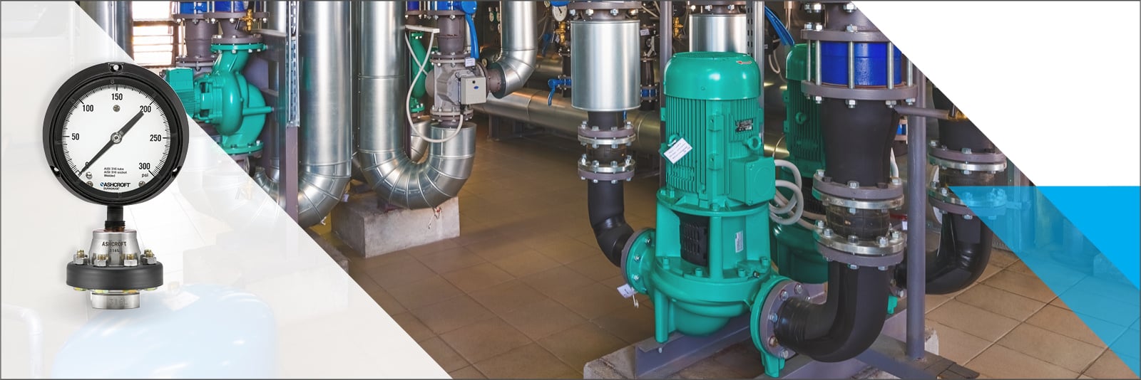
Diaphragm seals add error because process pressure passes through a flexible diaphragm and fill fluid before reaching the sensing element. Temperature-induced fill expansion is the biggest factor, followed by reduced accuracy at low pressures, slower response, and mounting position effects.
To minimize it:
- Use the largest practical diaphragm for better sensitivity.
- Keep capillaries short to limit fill volume and temperature exposure.
- Select a low thermal expansion fill fluid for your temperature range.
- Calibrate the instrument and seal together as one system.
Ready to learn more?
As you can see, a lot of factors go into determining the accuracy of pressure and temperature instruments. Check out the related resources below or contact us if you have specific questions. In the meantime, download our guide to determine the accuracy of your accuracy statement.
Topics:




.png?width=1600&height=534&name=choosing-pressure-switch-9factors_BLOG%20(1).png)
