

Subscribe now and get the latest blog posts delivered straight to your inbox.
.png?width=1600&height=534&name=Copy%20of%20Choosing%20Pressure%20Sensor%20for%20OHV_BLOG%20(3).png)
Electrical measurement drift can be caused by temperature changes, pressure or thermal cycling, mechanical stress, moisture, contamination, and changes within a sensor’s sensing element or electronics. However, not every changing reading is true drift. Wiring problems, electrical interference, and installation conditions can create errors that look like drift even when the sensor itself has not changed.
In a critical process, that distinction matters. A small measurement error may affect a control decision or process condition long before an instrument fails outright.
Pressure transducers, RTDs and thermocouples can each develop measurement errors for different reasons. Understanding where the change originates can help you determine whether the problem requires recalibration, installation changes or sensor replacement.
Read this article to learn:
- What measurement drift means and how it differs from other measurement errors
- What causes pressure transducers, RTDs, and thermocouples to lose accuracy
- How electrical interference and installation conditions can affect readings
- How to troubleshoot a changing measurement
- What to verify before returning an instrument to service
What does measurement drift mean in a critical process?
Measurement drift is a gradual change in an instrument’s output relative to a known reference, even when the measured condition has not changed. True drift typically develops over time. A reading that suddenly jumps, fluctuates or changes when nearby equipment operates may instead indicate electrical interference, a loose connection or an actual process change.
For a pressure transducer, measurement error may appear as:
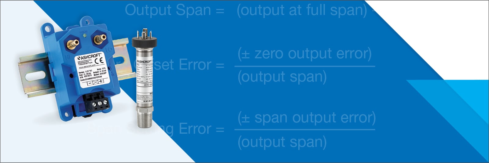
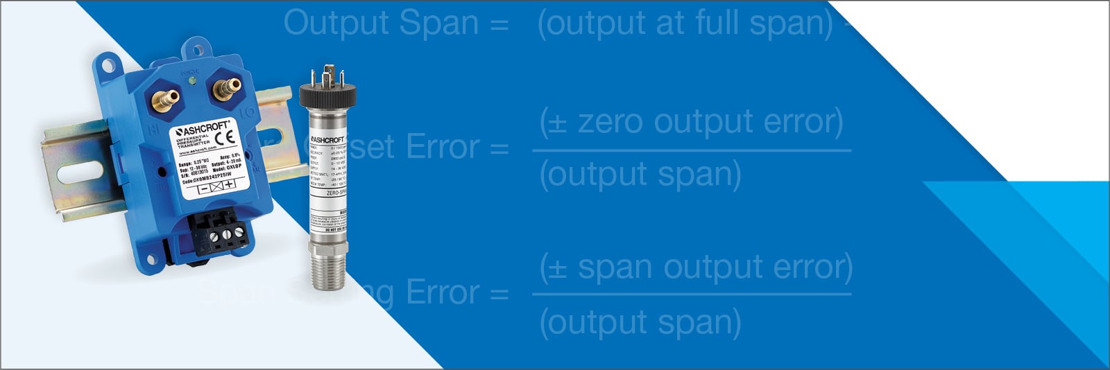
- Zero offset: An output error at the bottom of the calibrated measurement range.
- Span error: An output error at the full-scale measurement point.
- Drift: A gradual change in output that develops over time due to factors such as temperature, humidity, mechanical stress or repeated pressure cycling.
Keep in mind that the bottom of a pressure transducer’s range is not necessarily 0 psi. For example, a compound-range transducer may begin at vacuum. Before identifying a deviation as drift, compare the instrument against a suitable reference at multiple points across its measurement range.
What causes a pressure transducer’s output to change?
A pressure transducer’s output can change when environmental conditions, repeated pressure cycles or mechanical stresses affect the sensing element or electronics.
Some of the most common contributors include:
- Temperature: Changes in ambient or process temperature can affect sensor materials and electronic components, shifting the output. When reviewing specifications, distinguish between the instrument’s compensated temperature range and its broader operating temperature limits.
- Pressure cycling: Repeated diaphragm deflection can gradually affect the sensing element and shift its baseline measurement.
- Humidity and moisture: Moisture can affect electrical connections, insulation and other components within the measurement system.
- Mechanical stress and vibration: Repeated pulsations can affect connections or the sensing assembly and contribute to changing measurements.
- Component changes over time: Electronic and sensing components can experience gradual changes that affect zero, span or overall output.
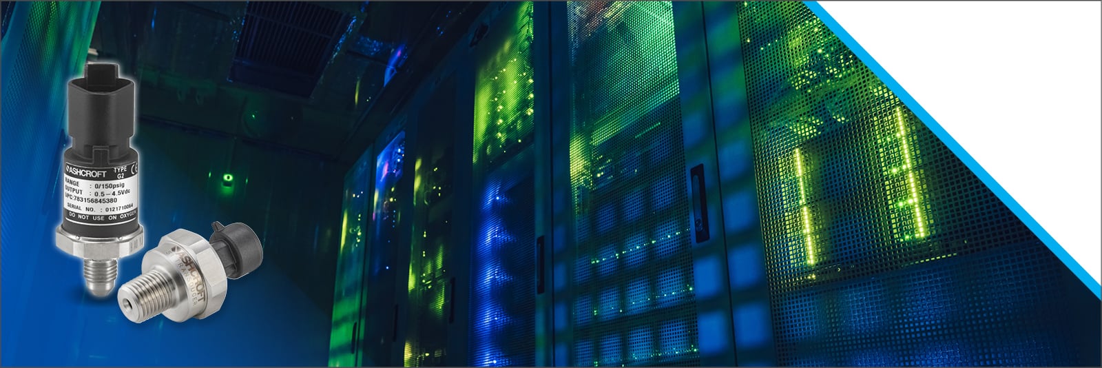
Some Ashcroft® pressure transducers, including E2G, CXLdp and DXLdp options, provide zero and span adjustment. However, first determine why the output changed. An adjustment may correct an offset, but it cannot repair a damaged sensing element or eliminate an installation problem.
Why can electrical interference be mistaken for measurement drift?
Electrical interference can change a pressure transducer’s output without a corresponding change in pressure. Unlike persistent drift, the error may appear only when nearby equipment is operating.
Motor drives, power wiring, and radio-frequency sources can introduce electromagnetic interference (EMI) or radio-frequency interference (RFI). In semiconductor and other electrically demanding environments, high-power equipment can also introduce additional sources of interference.
Look for patterns such as:
- A reading that changes when a motor or drive starts
- A signal that becomes unstable during a particular equipment cycle
- A measurement that returns to normal when nearby equipment shuts down
- An error that disappears when the instrument is tested under controlled conditions
If you see these patterns, inspect cable routing, shielding, grounding, and electrical connections before recalibrating the sensor.
Ashcroft E2 and G2 pressure transducer designs, for example, are designed to limit the effects of EMI/RFI. However, the complete installation still needs to be considered because interference can enter the measurement path outside the sensor itself.
Why do RTDs and thermocouples lose accuracy over time?
RTDs and thermocouples can both develop measurement errors, but the causes differ because the two technologies measure temperature differently.
What causes RTD measurement drift?
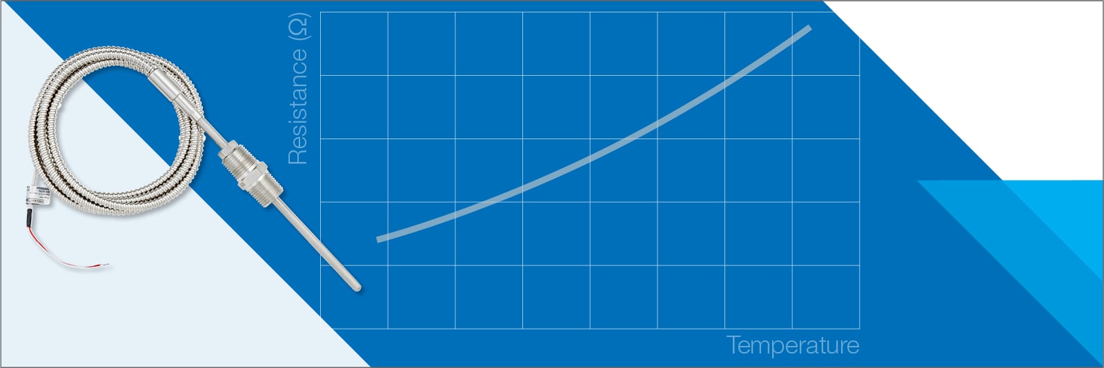
RTDs are known for stability, but the sensing element, wiring and surrounding environment can all affect the reading.
Common causes include:
- Moisture and corrosion: Moisture ingress can damage insulation, terminals and other sensor components, leading to unstable readings or calibration drift.
- Vibration: Repeated mechanical stress can weaken lead wires, connections or the sensing element.
- Wiring problems: Loose connections, damaged cables, and improper installation can produce false or inconsistent readings.
- Lead-wire resistance: This is especially important in two-wire RTD configurations, where lead resistance becomes part of the measurement.
- Long-term environmental exposure: Elevated temperatures and harsh operating conditions can gradually affect measurement accuracy.
What causes thermocouple drift?
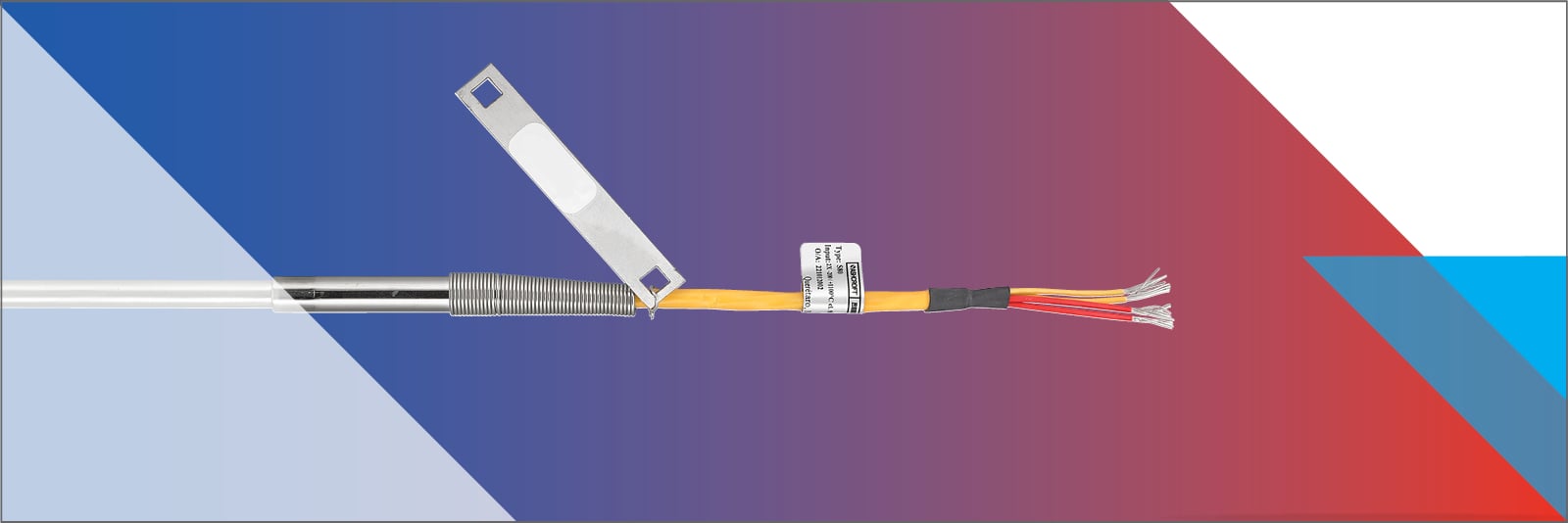
Thermocouple drift occurs when environmental or mechanical conditions alter the properties of the thermocouple materials.
Common causes include:
- Sustained high temperatures
- Thermal cycling
- Mechanical shock and vibration
- Oxidation and corrosion
- Contamination
- Aging of thermocouple materials
At elevated temperatures, these effects can accelerate. Changes to the thermocouple alloys can alter the millivolt output used to determine temperature.
A calibration check can identify how much error exists by comparing the thermocouple with a known, traceable reference under controlled conditions. However, calibration does not reverse permanent changes to the thermocouple material. If the resulting error exceeds the allowable process tolerance, replacement will be necessary.
How can installation affect very-low-pressure measurements?
In very-low-pressure applications, tubing length, temperature, and the pressure reference itself can affect the pressure reaching a differential sensor. That means the displayed change may originate in the measurement setup rather than the sensing element.
This is especially important in controlled environments where pressure differences may be measured in hundredths of an inch of water column. At these levels, seemingly small installation variables can become significant.
Before adjusting the transducer, inspect:
- Both high- and low-pressure sensing lines
- Tubing length and routing
- Temperature exposure along the tubing
- Connections and possible leaks
- The pressure reference used by the measurement
Sensor construction can also influence long-term stability. Ashcroft® Si-Glas™ technology uses a micro-machined silicon diaphragm and a differential capacitance design. Its sensing element is constructed without epoxies or other organic materials that could contribute to drift or mechanical degradation over time.
However, a stable sensing element cannot eliminate errors introduced elsewhere in the installed measurement system.
How do you find the source of a changing measurement?
You can find the source of a changing measurement by comparing the instrument against a known reference, then determine whether the pattern points to the sensor, electrical circuit, installation or actual process. Avoid making a calibration adjustment based on a single unusual reading. Instead, look for repeatability and compare the current result with previous calibration records when available.
First checks for apparent measurement drift
| What you see | Possible cause | First check |
|---|---|---|
| Repeatable zero or span error | Calibration shift or sensing-element change | Compare the output with a suitable reference at endpoints and intermediate points. |
| Signal changes when nearby equipment runs | Electrical interference | Compare the signal with equipment cycles and inspect wiring, cable routing and grounding. |
| Output changes with ambient temperature | Temperature effect | Review reference and compensated temperature specifications and repeat the test under controlled conditions. |
| RTD reading is intermittent or changes after moisture exposure | Wiring, connection or insulation problem | Inspect the sensor head, cable and connections. |
| Thermocouple error increases during high-temperature service | Aging, contamination or material change | Compare the sensor with a traceable reference at relevant temperatures. |
| Very-low-pressure reading changes with installation conditions | Tubing or pressure-reference effect | Inspect both sensing lines, temperature exposure, connections and process conditions. |
How often should you check an instrument for measurement drift?
There is no single calibration interval that applies to every pressure or temperature instrument. The number of times you check your instrument for drift depends on the application, operating conditions, required tolerance, and any applicable quality or regulatory requirements.
Calibration history can also help determine whether an instrument is remaining stable or gradually moving toward its allowable limit. For thermocouples, for example, Ashcroft recommends basing calibration frequency on factors such as operating temperature, environmental exposure, and required measurement tolerance.
Rather than treating each calibration as an isolated event, compare as-found results over time. A developing pattern can provide useful information about sensor condition and whether the existing calibration interval remains appropriate.
What should you verify before returning an instrument to service?
Verify the entire measurement path, not just the number displayed by the instrument. The goal is to confirm that the measurement meets the process tolerance under its actual operating conditions.
Return-to-service checklist
- Document the starting point: Record the as-found reading and the reference used to evaluate it.
- Identify the source: Determine whether the error originated in the sensor, wiring, electrical environment, installation or process.
- Address the cause: Repair wiring or installation problems, recalibrate where appropriate or replace a damaged sensor.
- Check more than zero: Verify the instrument at the test points required by the application rather than relying on a single measurement.
- Confirm process tolerance: Make sure the resulting measurement is suitable for the accuracy requirements of the application.
- Record the result: Keep the as-left readings so future inspections can reveal a trend rather than an isolated discrepancy.
Ready to learn more?
Measurement drift does not always mean an instrument has failed. A changing reading can originate in the sensing element, electronics, wiring, installation or even the conditions surrounding the measurement.
If you have questions about pressure or temperature measurement in a demanding application, explore the related resources below or contact us to speak with a product expert.

Topics:
.png?width=1600&height=534&name=Temperature%20Instruments%20for%20Power%20Generation_BLOG%20(2).png)